
Introduction
Stepper motors are commonly used in industry for very precise
applications, as they can be very carefully controlled via a
digital circuit (often through a computer). The precise nature
of a stepper motor means that they are often used in home
desktop printers, which require very precise movements in order
to produce a high-quality print. As a result, stepper motors are
often sought after within the flight simulator hardware
industry, as they are excellent candidates for controlling
high-quality instruments, such as airspeed indicators,
altimeters, vertical speed indicators, and much more.
 |
In fact, almost all commercial FS instrument
manufacturers (such as Flight Illusion, Seagull
Simulations, etc) use stepper motors. The only exception
is SimKits, who chose to use servo motors. Whilst servo
motors are easy to use and quite reliable, they are
often much more noisy and less precise than stepper
motors; hence why most companies favour the former. Unfortunately, with the many advantages of stepper motors there will always at least one disadvantage. Generally, suitable stepper motors are much harder to source than DC motors or servo motors, which can easily be purchased in local hobby shops and on the internet. Whilst stepper motors can be purchased online, the sheer variety and differentiating specifications of the motors makes it difficult for beginners to find the right motor for their application. Another slight disadvantage to using stepper motors is that they are more difficult to understand than other types of motors. Don't expect to just connect a simple power supply and see the motor spin around! A quick Google search will indicate that stepper motors are “brushless DC electric motors” than can be controlled via “open-loop” or “closed-loop”. |
Although it is a rather abstract way of picturing how stepper motor works, if one can imagine an everyday shopper; a bargain hunter on the look out for deals and low priced goods.
This shopper will move from one supermarket to another to catch the best deals whenever they are on (for the purposes of this explanation assume that only one supermarket has one offer on at once). Each time the shopper moves from one supermarket to another, we call this a “step”.
 In this first picture, our shopper is attracted towards “Save-a-lot”, as they have the lowest prices... |
 Now that “save-a-lot” have stopped their deals, our shopper is no longer attracted to them and moves onto “Tesco”, who have now opened their deals to the public... |
 The shopper makes another step... |
 Finally, “Save-a-lot” re-open their offers and our shopper goes back to them. He has made on complete revolution now, having “stepped” 4 times. The red arc shows his path... |
 As one can see, the red arc the shopper has made has formed a circle. Likewise, as a stepper motor turns through 360 degrees, it makes a circle. |
|
This is why this rather abstract way of explaining how a stepper motor works is actually quite relevant. The following animated picture, available on Wikipedia, shows how a stepper motor turns. The similarities with the above example are clear; the shoppers have been replaced with toothed electromagnets, and the shopper himself has been replaced by a gear (which, for our purposes, would probably be connected to some sort of airspeed indicator or other instrument).

The principle is exactly the same. The toothed electromagnets on
the outside are energized, and thus the central gear is
attracted to them one by one as it makes a complete revolution,
turning in what is called “steps”. Of course, there are very few
stepper motors that only have 4 steps per turn; think how
useless that would be for designing a flight simulator
instrument! As a result, there are many different types
available, each with differing voltages, current ratings, steps
per turn, and even with different polarity (unipolar and
bipolar), the latter of which is discussed in the next
paragraph.
Of all the stepper motors available on the market, the one thing
you can be sure of is the polarity. Unlike things like number of
steps per turn or voltage/current ratings, a stepper motor can
only be Unipolar or Bipolar. Unipolar stepper motors are rather
simple to operate; they work exactly like the example above and
there are only a few deviations from this rule.
Bipolar stepper motors are much more complex to operate, but
will still offer a similar end result. Bipolar stepper motors
often have what is called a “H-bridge” arrangement, which allows
a specific voltage to be “applied across a load in either
direction” (see Wikipedia, “HBridge”:
http://en.wikipedia.org/wiki/H-bridge
![]() ).
).
Further delving into the technicalities of each motor type would
deviate somewhat from the intentions of this review, and so I
have kept such explanations contained within the above paragraph
only. Needless to say, one should be familiar with the “pros and
cons” of each motor type. Generally:
– Unipolar motors are simpler, cheaper, and are used for
low-speed, low-torque
applications (ie perfect for most flight simulator instruments)
– Bipolar motors are more complex and more expensive, but offer
much more torque and
speed than Unipolar motors (perhaps suitable
for more demanding
FS applications,
perhaps a helicopter rotor gauge)
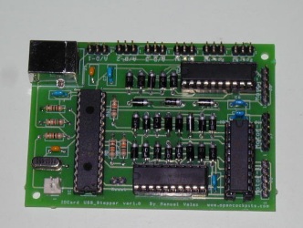
The Opencockpits USB Stepper motor card has been designed
specifically for use with flight simulation, and allows users to
apply the benefits of stepper motors to everyday cockpit building
applications, such as an airspeed indicator or altimeter.
Thankfully, the Opencockpits card is quite flexible, and
supports both Unipolar and Bipolar stepper types, with numerous
current and voltage ratings (see product specification below).
Through the use of the USBStepper motors card, cockpit-builders
can design their own aircraft gauges and interface them to
flight simulator 2004, flight simulator X, or even X-Plane.
Product Specifics and Information
The Opencockpits USBStepper motors card can be purchased through
the Opencockpits shop for 40 Euros + VAT and Shipping (where
applicable). This price means that this card is one of
Opencockpits' more expensive offerings, with most of their other
products retailing around 25-30 Euros +VAT & Shipping. Like all
Opencockpits cards, a USB cable is included as standard; a nice
gesture these days, as most companies require you to purchase
one externally!
Alternatively, the card can be purchased from Aviation Megastore
http://www.aviationmegastore.com
![]() Personally I prefer to buy
direct through
Personally I prefer to buy
direct through
Opencockpits, as their postage prices tend to be more reasonable
than Aviation Megastore's.
To my knowledge, Aviation Megastore is the only official
retailer for Opencockpits products, so if you don't want to buy
from Opencockpits directly, you don't really have much more
choice!
 |
The USBStepper motors card boasts the following specifications: – Able to control up to 3 stepper motors, with support for 3 optical sensors (see later in review). – Supports 3 analogue inputs (potentiometers), which can be used for position feedback. – Connects directly through the USB port of a PC; no need to install any drivers. – An external power supply (up to 36V and 1A) can be connected if required (not included). – Full support for both Unipolar and Bipolar stepper motors. – Completely interfaced to FS2004/FSX/X-Plane through the SIOC (freeware) interfacing system. |
|
| The main advantage, of course, is being able to perform all of the complex operations listed in the introduction through a simple USB port! | ||
Preparation and Installation
Like most hardware products, a little preparation is required before you are able to start using them.
The first and most obvious step with an Opencockpits product is to first check if the latest version of SIOC has been installed. At the time of writing this review, I can confirm version 3.7B1 works perfectly, although I am aware that there has been a very recent release of SIOC which boasts a few advantages over its predecessors. SIOC is developed by Opencockpits and is completely free of charge (to download, see the link at the “downloads” section at the end of the review).
Another step, which may seem even more obvious, is to actually locate a working stepper motor. The most common source of stepper motors for FS related projects is usually from old, unwanted printers. In fact, one of the stepper motors I used in this review was sourced from an old printer of mine, and it works perfectly. If necessary, a stepper motor can be purchased online or perhaps at a local electronics shop.
It is also necessary to download “IOStepper.exe”. This is yet another freeware program developed by Opencockpits exclusively for the USB Stepper motors card. This program works alongside SIOC (providing a bridge between the stepper motor and SIOC), and is very easy to use.
After securing the basics, I proceeded to plug the USBStepper motors card plugged in.
Further adding to the reliable impression I have received from Opencockpits from previous reviews, the card was recognized and installed automatically; a true “Plug'n'Play” unit.
Once installed, the card should have a device entry visible in the main SIOC window (open the SIOC executable file and look in the main device window).
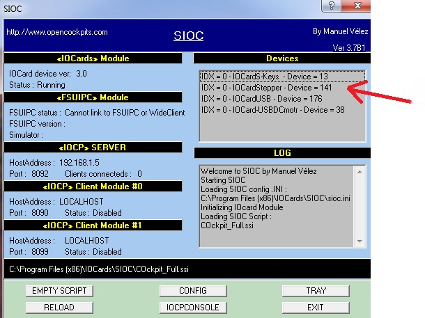
[NOTE: In the above photograph, you can see other devices
listed. This is because I own an extensive amount of
Opencockpits products, and as such they also appear in the
device window!]
I also prepared a simple 5V power supply to plug into the
USBStepper motors card. As previous mentioned, this is only
necessary if you need external power for your stepper motor.
Whilst my stepper motors didn't require external power (the
power through the USB port was enough), my computer has a high
amount of USB connections; and thus I didn't want to experience
a “power droop” during operation. It was also a good test of how
easy using a power supply with the card was. Unfortunately, I
had to purchase my own plug to connect to the power supply pins.
In the past, I had been supplied this pin by Opencockpits within
the card's packaging.
After checking everything was ready, it was time to install my
stepper motor...
Installing a stepper motor into the USBStepper motors card
Depending on the type of stepper motor (Unipolar or Bipolar),
each will have a different wire configuration. This means that
some stepper motors can have up to eight wires; some only have
four. As such, it is important to differentiate between
different types so that one knows how to connect it to the
USBStepper motors card.
Although most stepper motors have some sort of label identifying
their type and wire configuration, some (like mine) do not, and
thus I had to refer to Opencockpits' documentation to find out
how the function of each wire on my stepper motor.
In a nutshell, the documentation recommends the use of a
multimeter to measure resistance between the coils on the
stepper motor. The exact instructions can be found in the
Opencockpits manual (see link at end of review). Personally, I
do not think the manual explains this well enough; however there
are plenty of tutorials on the internet detailing how to find
wire functions of a stepper motor.
NOTE: The above method will only find out the function of each
wire. If you are unsure if your motor is Unipolar or Bipolar,
then the following rules usually apply:
– A motor with 5 wires is Unipolar
– A motor with 6 wires is Unipolar (same as above but has 2
common wires of the
same colour)
– A motor with 4 wires is Bipolar
Through the application of all of the above instructions, it is
possible to find not only the motor type, but also identify each
individual wire and its function (ie identify each “coil” and
find the “common” wires). The wires of a stepper motor are often
referred to as “windings”; so don't be thrown if you see this
term.
Once each wire has been identified, it is possible to connect
the motor to the USB Stepper motors card. This is quite a tricky
process, as unless you have some sort of plug that fits the
exact pin configuration of the USB Stepper motors card, you will
have to hand-solder each wire into place; with costly
consequences if it goes wrong.
The following diagram supplied by Opencockpits (extracted from
the manual) shows how Stepper motors should be connected to the
USB Stepper motors card:

[NOTE: The motors are the right-hand side are the stepper
motors. The connections along the top show how potentiometers
(variable resistors) and optical sensors should be connected.
These are explained in more detail later.]
On the above diagram, three separate stepper motor connector
blocks can be seen on the right hand side. The diagram shows how
to connect a Unipolar 5-cable, Unipolar 6-cable, and a Bipolar
stepper motor. It should be noted that the motors don't HAVE to
be connected to the same slots as the above diagram; ie a
Bipolar motor can still be plugged into the top slot, provided
the wires are connected correctly. The actual wires, however,
are the same for each connector block; ie a Unipolar 5-cable
motor will ALWAYS have its “common” wire attached to the top
pin.
Whilst the diagrams in the manual are relatively clear, I do not
think that the textual explanations supplied within the manual
are good enough. It should be noted however, that Opencockpits
are a Spanish organization; and thus complicated explanations
may not be as well explained as possible.
If you have followed the instructions correctly, you should end
up with something like this:
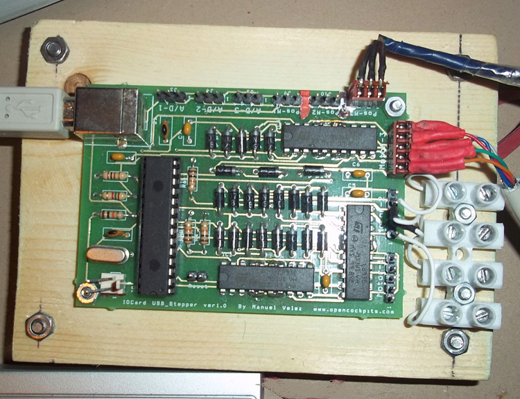
[NOTE: In the above photograph, you will see that an optical sensor has
been installed on one of the terminal blocks at the top of the
card. This is NOT a stepper motor. My (Unipolar) Stepper motor
is plugged into slot three; the 5-pin slot at the top right of
the card. The 5 pin slot halfway up the right-hand side is in
use with another stepper motor.]
I have also mounted my card onto a wooden board. This is because
the underside of the USBStepper motors card has exposed metal
solder joints, and it is a good idea to make sure these are
“protected” and not touching another conductor. Furthermore, as
with all circuit boards, you should NEVER rub it against any
sort of carpet-like material, hence why wood is a good
candidate.
Once the stepper motor has been installed, it is time to install
the optical sensor.
Installing an Optical Sensor
[NOTE: An optical sensor MUST be installed in order for a
stepper motor to function correctly. I was under the (correct)
impression that stepper motors could be operated “open-loop”
(without feedback); they can be, but the USB Stepper motors card
does not support this feature. The manual does not explain this
particular fact well enough!!!]
The USB Stepper motors card requires the installation of an
Optical sensor for position feedback. If necessary, a
potentiometer can be used for feedback; however optical sensors
are much better suited to stepper motors than potentiometers
are.
Optical sensors for stepper motors function in the exact same
way as a “finish line” at the Olympic games, or at a horse race.
They simply tell the USB Stepper motors card how long it took for
the needle to do a “complete lap” of the stepper motor at a
specific speed (more specifically, it tells the card “how many
steps per turn” the stepper motor has).
The Opencockpits manual states that the RS 305-560 optical
sensor should be used. This optical sensor can easily be
purchased online or at a local shop; it is a fairly well-known
optical sensor.
The optical sensors communicates with the stepper motors card
through voltage information. A beam of light streams between two
points on the sensor. When this beam is uninterrupted (ie it
streams from “A” to “B” without hitting any obstacles), a 5V
signal is produced and sent to the USB Stepper motors card. When
this beam is interrupted (ie “cut” with the needle of a gauge),
then a 0V signal is sent to the card, and the software is told
that the gauge's needle has hit the zero mark.
As a result, optical sensors are usually installed so that the
beam is cut when the needle reaches its “zero point” (for
example, 0 knots on an airspeed indicator). This makes
calibration much easier within software, as you can literally
state that “zero = zero”.
Installing an optical sensor is simple in principle but tricky
in nature. As long as one remembers to exactly align the sensor
with the “zero-point”, and ensures that the needle cuts the
light beam perfectly, there should be no nasty surprises when
operating a stepper motor.
Potentiometer Supporting
[NOTE: This section is not necessary if you have installed an
optical sensor (see above)] Potentiometers, or variable
resistors, are often used within cockpit building to provide
feedback for instruments and auto-throttle systems. This is
because, as the potentiometer rotates, the resistance increases
(or vice-versa), and so an interfacing program (in our case
SIOC) can tell the position of a device by cross-checking the
resistance value with a usermade script.
For example, imagine we have built an airspeed indicator. We
have designed a SIOC script that controls the airspeed
indicator, and we ask SIOC to use a potentiometer for position
feedback, which can be explained thus:
USER: “SIOC, when the Potentiometer has a resistance of 10K
Ohms, we're at 200 Knots”
SIOC: “10K Ohms detected; therefore 200 knots. FSX is only
showing 190 Knots. Adjusting
motor accordingly...”
The above “example” sees SIOC being given a value of 10K Ohms
(which equals 200 Knots on the ASI's faceplate), and then
reading the FSX knots value. SIOC realizes that FSX is only
showing 190 knots, and so it adjusts the stepper motor
accordingly.
Potentiometers can be used as an analogue-alternative to an
optical sensor. As a result, Opencockpits have thoughtfully
provided three potentiometer ports on the USBStepper motors card
to accompany the three available stepper motor slots.
It should be noted however, that the Opencockpits manual does
not recommend the use of Potentiometers (and, in fact, omits
them entirely from the whole manual). Personally; I am in two
minds regarding the matter. Whilst it is definitely true that
optical-sensors are much more precise, they are extraordinarily
delicate and difficult to set up (as previously explained).
Potentiometers are much simpler to operate and understand, and,
in fact, are actually more suitable than optical sensors for
some applications; primarily within an autothrottle system.
It is impressive to see that Opencockpits are providing support
for Potentiometers; proving that the USB Stepper motors card is
designed to be as flexible as possible.
NOTE: Whilst there has still been no testing software
released, the release of SIOC version 4.0 has allowed users
to test Potentiometer readings without having to use a SIOC
script. This can be done by using the "SIOC Monitor" option
available in the main SIOC window.
Testing and Operating the USB Stepper Motors Card
General tests and operation of the USB Stepper motors card can be
achieved through the use of two programs (previous mentioned).
These are:
– SIOC (v3.71B1+)
– IOStepper.exe (v0.2)
Both of these programs can be downloaded free of charge from
Opencockpits' website. They are very easy to install; a simple
double click on the executable file will start the installation
process.
Before beginning the process of actually getting the stepper
motor to move, a SIOC script should be constructed first. This
simple script provides the bridge between stepper motor and the
IOStepper.exe testing program. Thankfully, creating such a
script for the USB Stepper motors is VERY easy, especially when
compared to other Opencockpits products, such as the displays
card or USB LCD Card.
SIOC scripts should be written in .txt (text file) format,
before being compiled by the SIOC program to use with the card.
Microsoft notepad is the most appropriate application for this
task; but, if really necessary, you can use your own word
processor that produces .txt files. Only one line of code is
needed within the SIOC script, as detailed in the following
annotated diagram. The annotations explain the purpose for each
“snippet” of code.
CLICK TO ENLARGE
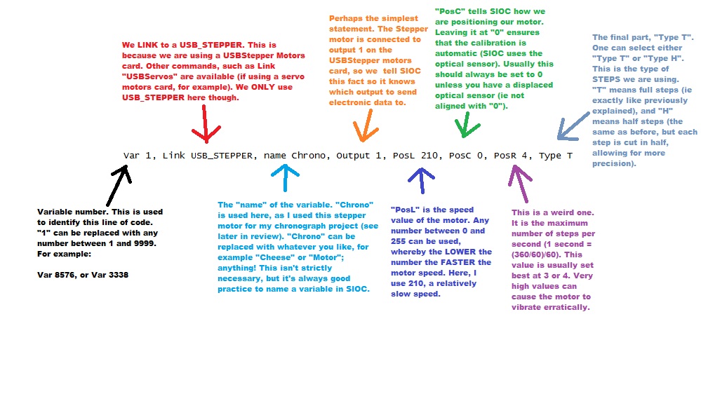
Please note, the above diagram is very detailed and “over the
top”. It would be perfectly simple just to copy the above line
of code into notepad and save it. The above diagram is designed
to be a reference should you wish to explore SIOC further.
To compile a .txt file, click the “config” button on the SIOC
main window interface. The configuration window should then
appear. In the config window, click “file”, “import”, and then
locate and import your .txt file. Once compiled, a large “OK”
should be visible, and you can save the SIOC file (now called
.ssi) into the SIOC folder, or wherever you like should you wish
to keep a backup copy.
The compiled SIOC file must be saved in the main SIOC folder to
be used, and must be referenced in the “SIOC.ini” file. The
“SIOC.ini” file is found in the main SIOC folder, and when
opened up in notepad, will contain many lines of code that
configures the SIOC program. Ensure that the
“Configuration_File=X” is set to the name of your compiled SIOC
file (where the X represents the name of this file, following by
the suffix “.ssi”; eg, “cheese.ssi”).
Please note, the information given here on how to use SIOC and
how to compile a file is rather brief, since this is a review
and not a SIOC guide.
For more information on SIOC, I suggest
you head over to Nico Kaan's website. Nico Kaan is often
referred to as the “SIOC guru” in the FS community, and his
website contains (literally) thousands of SIOC guides and
examples for you to use. A link to Nico's site is provided at
the end.
Once a suitable SIOC file has been compiled and saved, simply
start SIOC and then start the “IOStepper.exe” application. The
stepper motor should then turn twice through 360 degrees (ie
cutting the optical sensor twice), and then stop. Once this
procedure is complete, SIOC will then know how many “steps per
turn” that specific motor has. Please note; SIOC saves no such
information, and as a result, this procedure must be repeated
EVERY TIME SIOC is started, should you wish to use your stepper
motor.
Sending Information to the Stepper Motor
Interestingly, Opencockpits have designed the USB Stepper motors
card to receive information in terms of degrees to turn, rather
than in terms of number of steps.
Phrased differently, if you wish to turn your stepper motor
exactly half way, you must send to it a value of “180” (180
degrees, have a full rotation). For example:
A stepper motor has exactly 100 steps per turn. The user sends
the stepper motor a value of “180”, and the stepper motor moves
50 steps, or exactly halfway. If sent a value of 360 or 0, it
will return to the “0” point by the shortest possible path.
Personally, I am very pleased with this approach to controlling
the USBStepper motors card. It is very simple to understand, and
makes interfacing to FSX/FS2004/X-Plane so much easier. The
following script is a simple example of how to interface an
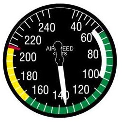
airspeed indicator (ASI) using
the USBStepper Motors Card. The first picture is a digital
representation of our ASI gauge.
It turns through 240 knots in 340 degrees.
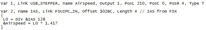
The following things can be noted in the above script:
“Var 2, name IAS, Link FSUIPC_IN, Offset $02BC, Length 4”
- This
line defines the indicator airspeed FSUIPC offset for FSX. The
offset is code 02BC (which must be preceded be the symbol “$” in
SIOC), and it has a Length of 4. All such information can be
found within the FSUIPC SDK documentation. The command
“FSUIPC_IN” is used, as we are READING the offset (the command
“OUT” is used when WRITING to the offset).
“L0 = DIV &IAS 128” - This line of code divides the airspeed
offset by 128. This is because the IAS offset is multiplied by
128 by FSUIPC when it reaches SIOC, so we must do the opposite
to get a correct value (or else our IAS value will be 128 times
too high!).
“&Airspeed = L0 * 1.417” - This converts between knots and
degrees. Since 340/240 = 1.4166666 (1.417), we multiply the FSX
IAS Knots value to 1.417, and send this mutiplied value to the
stepper motor. For example, at 100 knots, the stepper motor will
move 141 degrees; approximately between a quarter-way and
half-way of full rotation.
All other script components, such as the “curly brackets”, are
part of the core SIOC understanding, which is explained
perfectly on Nico Kaan's website (see link at end).
This script will successfully interface an airspeed indicator to
FS2004/FSX using the USB Stepper motors card. Of course, the
exact same logic can be adapter and applied to other gauges,
such as a VSI gauge or fuel gauge. The purpose of this section
is to demonstrate how just 5 lines of code can produce a
perfectly working instrument; at a fraction of the cost of a
“pre-built” unit.
Reliability and Problems
Generally, it must be said that the USB Stepper motors card
performs outstandingly without issue. There are, however, a few
occasional “glitches” (as I'm sure they're just small
unintentional problems) that can occur. Firstly, the optical
sensor feature on the card doesn't seem to always work
perfectly. I had a perfectly working opto-needle configuration
working with the USB Stepper motors card, and then suddenly, the
card would no longer recognize the opto-sensor's inputs. After
testing the sensor with a multimeter, I quickly learned that it
was the card at fault and not the sensor.
Having no idea what had happened, I simply “widened” the needle
that cut the opto-sensor's beam. To my amazement, this fixed the
issue. It seems a “wider” needle (ie the opto-sensor reads 0
Volts for a longer period, as the needle is over the beam more
often) fixed the issue. This problem has never since
re-occurred, and I'm not sure what caused this apparent lack in
“needle tolerance”!
Although not so much a problem, the PIC chipset(s) on the card
seem to get very hot when in operation for awhile, to the point
where they are severely uncomfortable to touch (around 50-60
degrees). Unfortunately, this is unavoidable; most products
which operate at high current for long periods of time will
suffer from some sort of heat problem at some point. It is,
however, possible to install a home-made heat-sink solution if
absolutely necessary. Personally however, I feel that letting
the card “have a rest” and restricting unnecessary use is the
best cure!
Documentation
As with all Opencockpits products, the USB Stepper motors card is
supplied with a PDF manual, which can be freely downloaded from
Opencockpits' product page.
Unfortunately, the manual isn't as impressive as the product
itself, which is a shame. The manual seems to be missing
specific key components (such as how to install and use and
opto-sensor), which are quite frustrating; especially when
dealing with such a complex product.
However, if you are rather confident with using such delicate
circuitry, then the manual perfectly suffices as a guide to help
course you through the steps needed to set up the card.
Even for less confident people, the manual seems to cover the
absolute basics; but that is all – I feel that the manual could
do with a bit of a re-work.
Incorporating the USB Stepper Motors Card into Cockpit-Projects
As a means of being able to demonstrate the USB Stepper motor
card's ability, Opencockpits kindly supplied me with a Boeing
737 Chronograph “kit”, which I planned to use alongside the
USB Stepper motors card.
Since I am building a Boeing 767 cockpit, you may be thinking,
“why use a 737 chronograph”? The differences between the two are
very subtle; and they function in the exact same way.
Furthermore, 767 chronographs are rare and difficult to obtain;
hence why I am happy to use a 737 chronograph.
The following digital diagram outline the fundamentals of the
Boeing 737/767 chronograph.

Please note, some buttons, like “SET” and the “+/-” buttons have
been excluded. This is because, not only do they have a
different function in the Boeing 767, but they are also not
simulated in any FS2004/FSX simulations.
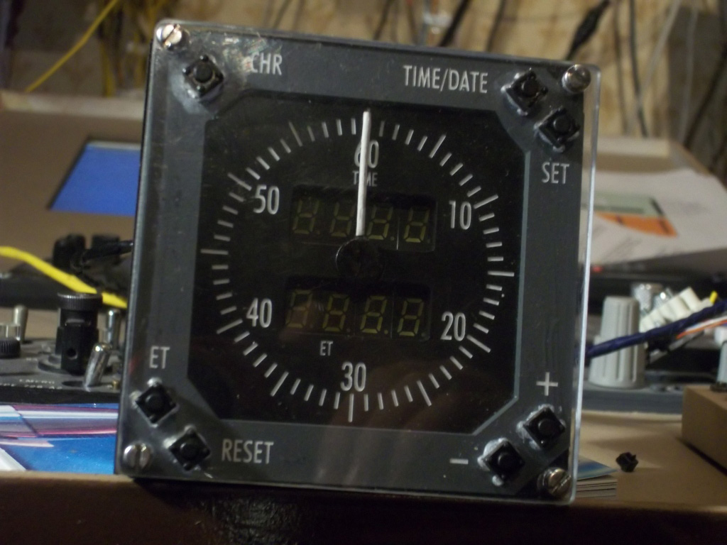
Although it took many months and weeks of painstaking work, my
chronograph was finally completed around December 20th 2011.
This is what it looks like:
 |
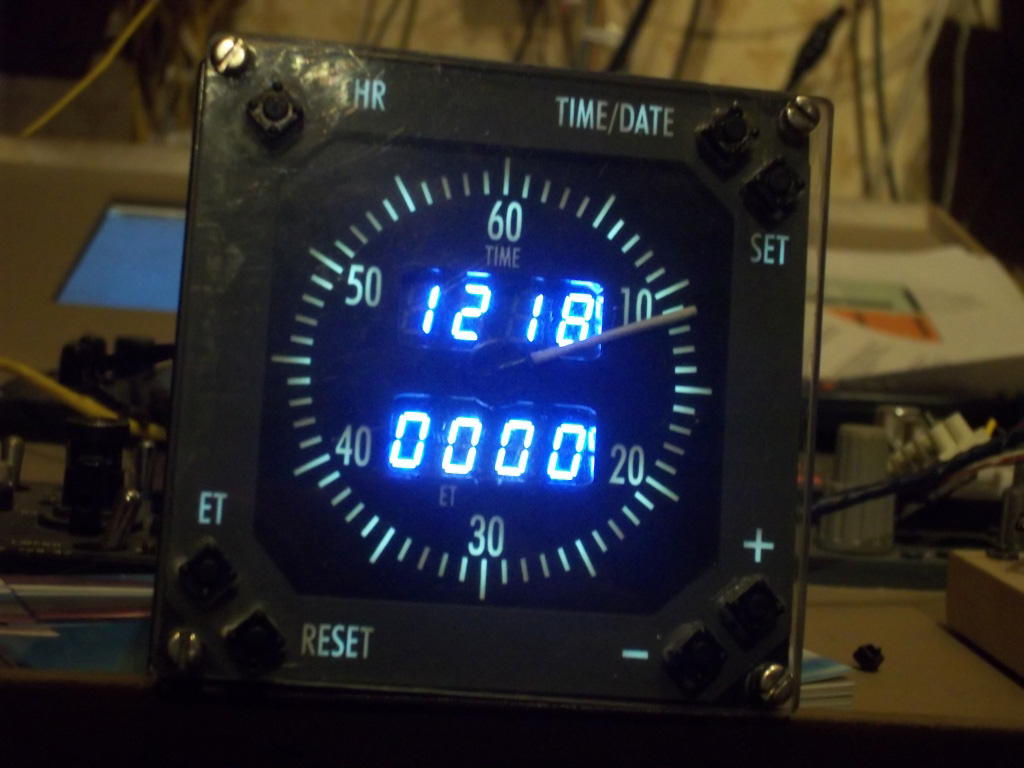 |
My chronograph is interfaced entirely using the Opencockpits USBStepper motors card; with the Opencockpits master card and 7-segment displays cards handling the buttons and displays, respectively.
The USBStepper motors card has been a fantastic aid in achieving my chronograph goal. It flawlessly turns my chronograph needle every time, without fail.
If you'd like to learn more about the operation of my chronograph and the USBStepper motors card, I have recorded a detailed video which covers all the in-depth technical details.
If you have any questions regarding my chronograph project (or
regarding this review), please do not hesitate to contact me.
Conclusion
The Opencockpits USB Stepper motors card provides cockpit
builders with a fresh approach to simple stepper motor
operation. Although considerably tricky to initally set up, the
card performs flawlessly and delivers cockpit builders with
outstanding results every time.
The card is perfect for almost any instrumental application, and
the inclusion of 3 analogue input slots proves that Opencockpits
are supporting various interfacing methods; useful for those who
aren't comfortable with optical sensors.
The card is very reliable and is exactly what the FS market
needs. The only negative aspect to the product is the
documentation and, perhaps, the very occasional opto-sensor
issues that I experienced.
A very well done to Manuel and the Opencockpits team!
![]() Verdict
Verdict
Pros:
– Very reliable
– Easy to script and program for
– Extremely useful; provides an excellent foundation for
building home-made instruments
– Support for both optical sensor and potentiometer sensor types
– Compatible with many different types and specifications of
Stepper motor
Cons:
– Occasional heat problems (50-60 degrees) when in operation for
long periods of time
– Although not a “fault”, the card only has three motor slots
available
– Opto-sensor issue (needle wasn't detected); however this
particular issue only happenedONCE
The USBStepper motors card is a credit to the Opencockpits team
and perfect for use by
anyone worldwide; professional cockpit builder or not.
My score? A Mutleys Hangar score of
8/10
![]()
Jack
Whaley-Baldwin
Review machine Spec: Core i7 920 OC @ 3.8 Ghz |
6Gb Tri-Channel DDR3 Ram |GTX285 Graphics |Windows 7
64bit Home Premium
|
Product Page
|